TAD Revolution One / Part 4 - casework and fine-tuning
While in the previous parts of the Revolution One journey I focused on the ideation, experimental modelling, and selection of parts, this penultimate part describes the baby coming to life. Theoretically, after all the hard work, it means clicking the things together and enjoy the music. Practically, this turned out to be the most difficult étape.
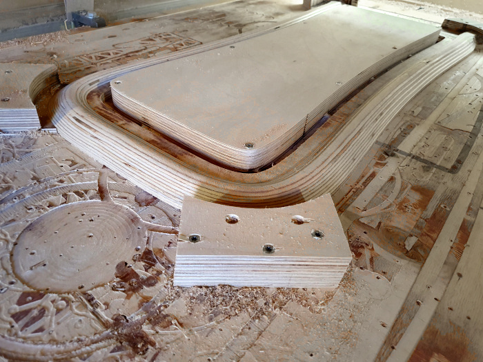
Milling of the ribs from birch plywood composite.
TAD Revolution One / Part 1 – Cabinets
TAD Revolution One / Part 2 – Crossover
TAD Revolution One / Part 3 – Crossover parts
TAD Revolution One / Part 4 – Casework and fine-tuning
TAD Revolution One / Part 5 – Finale
The Revolution One casework
The mission of drafting a case for the crossover was guided by two principles: To make the case as roomy as possible inside to accommodate all the large parts that were used, and to make it visually as little intrusive as possible. All attempts to design a box-shaped chassis with a small footprint resulted in two small refrigerators sitting next to the speakers; if prolonged shape was used to bring the height down, I got two coffins. In any case it was clear that the crossovers would become the second biggest audio components in the room. That’s why I started to think about a curved shape to lighten up the heaviness of their appearance.
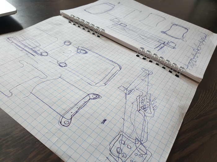
Some early sketches of the case.
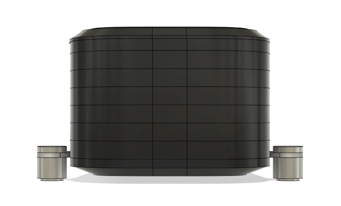
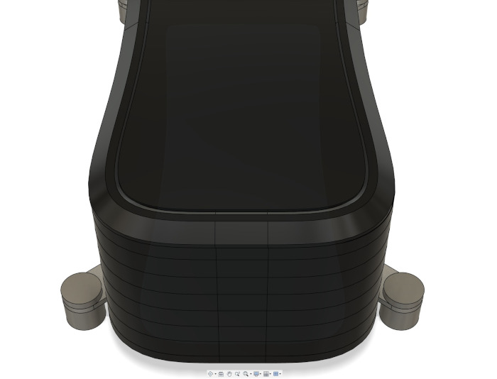
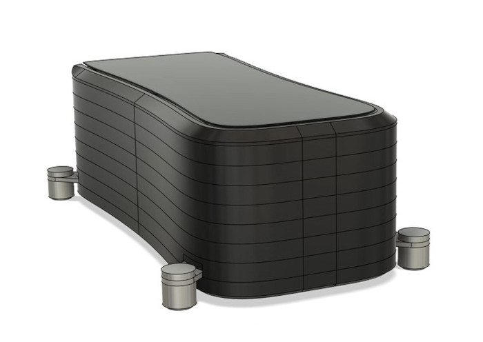
3D models of the case. The gentle curvature eliminated right angles and planes, and all edges were bevelled. The plates for the feet were inset into the chassis and were planned to protrude diagonally.
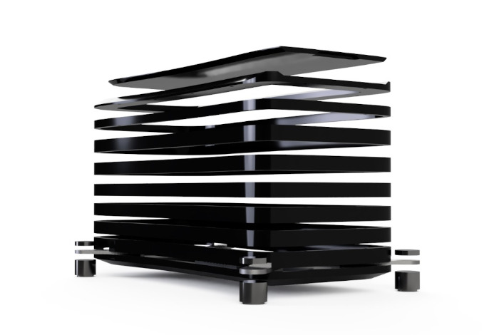
The expanded scheme of the Revolution One casework. In the picture, the individual horizontal ribs assembly can be seen.
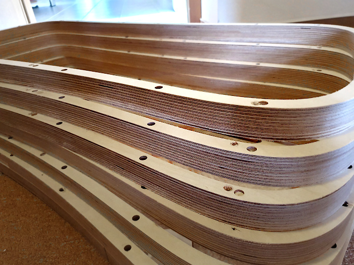
Luckily, for Silent Laboratories such a rather complicated shape represented no problem, for they build speaker cabinets by multi-axis CNC milling. The CNC cutter mills the case rib by rib from 30mm thick “biaxial composite” boards (which is a fancy expression for high-density birch plywood). It took 16 machine-hours to mill all the ribs. After that, they were stacked one atop another and glue-pressed by 30 tons of hydraulic pressure. This way the case could have thinner walls, no flexion and was very rigid. The final structure was then hand-sanded and prepared for coating.
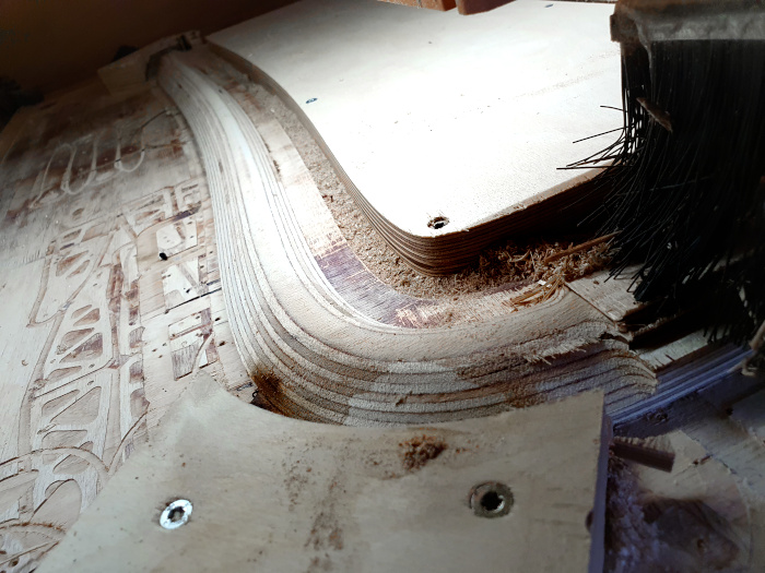
The top rib is about to be finished.
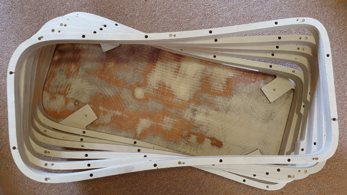
The ribs stacked atop each other without glue.
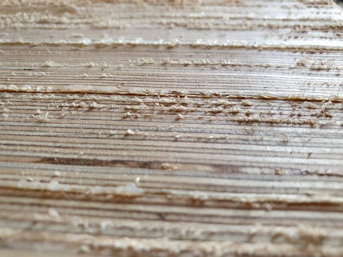
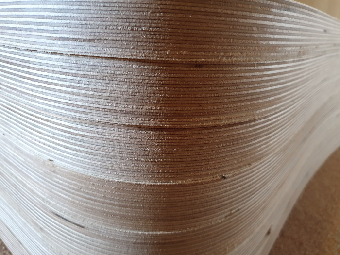
The glued surface prior to sanding.
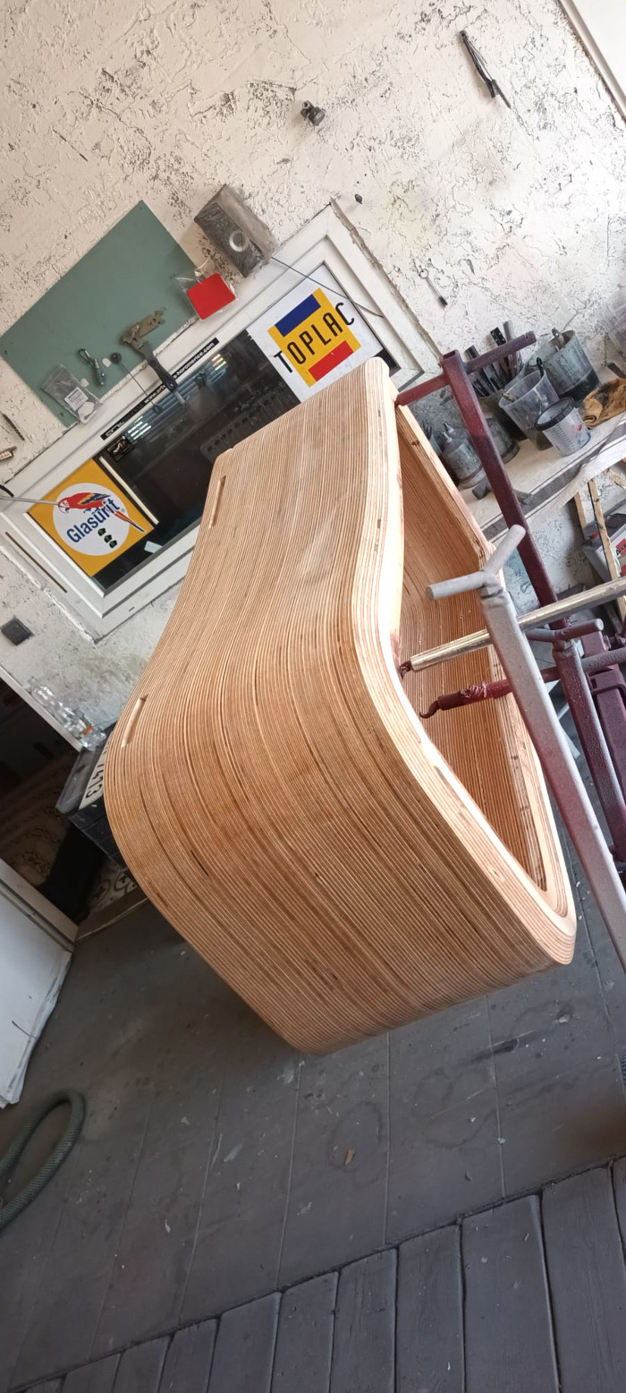
Ready for paint job.
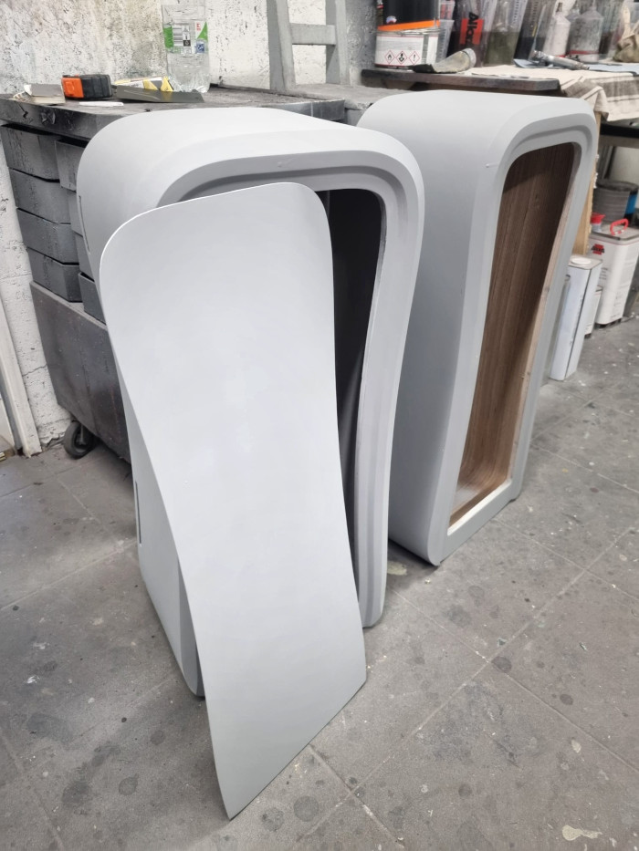
After the base coat.
For the top coat, I wanted stealth looking black on black paintwork. The raw case was impregnated with epoxy resin, 5 layers of filler were used and sanded down, then 2 layers of basecoat and 3 layers of topcoat were applied, plus a layer of antiscratch coat. It took 2 weeks to finish the paint job.
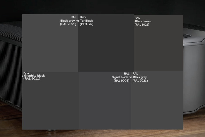
Not all blacks are equal. I pre-selected the colours on the screen and then purchased a spray can of each to test how it would appear in the room.
Stainless steel hardware
Dealing with resonances is always a challenge. Those who follow Audiodrom’s endless exploration of isolation devices (Isolation Systems series) know that I favour hard supports (energy transferred away from a component through mechanical assemblies) to soft solutions (energy stored in elastic materials). Your findings may be different, but I yet have to hear a good “sounding” elastic isolation support in my room.
However, there are exceptions. For instance, I admit that elastic system of Isoacoustics Gaia under Marten speakers makes no harm to these nice and supple sounding speakers. I am not a Stillpoints worshipper either, although they are a typical and highly regarded representant of the hard school. No doubt their models have positive effects, especially if your playback chain is on the more muffled and darker side of spectrum, but to my ears Stillpoints induce a spike in the upper presence region, which cumulatively leads to overhyped sound.
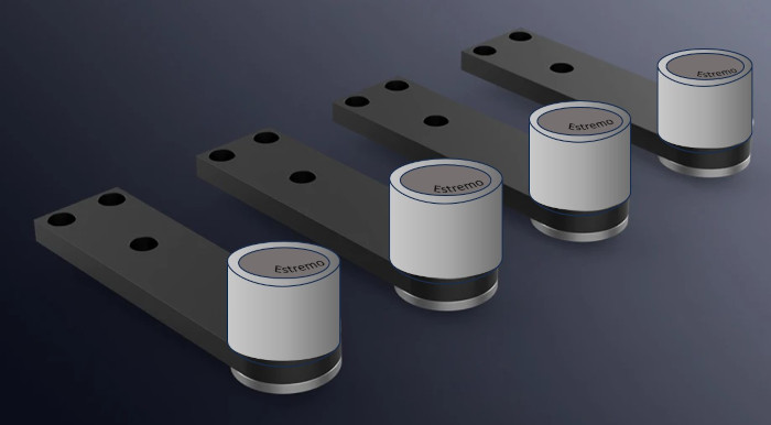
For the Revolution One, AAI isolation pads were my go-to feet, for I consider them to be the most balanced solution of all I have tested. I am not going to elaborate on how the AAIs are designed, I recommend reading the aforementioned article instead. We drafted the complete hardware kits with the guys from AAI. The feet got the IST Estremo-level treatment, the same as the wires inside. To fight my AAI bias, I also loaned two sets of Isoacoustics Gaia II, so that I could test them under the Revolution One crossovers too. Who knows, maybe I will be in for a big surprise.
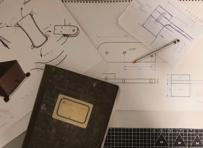
Initial sketches
One of the 3D models
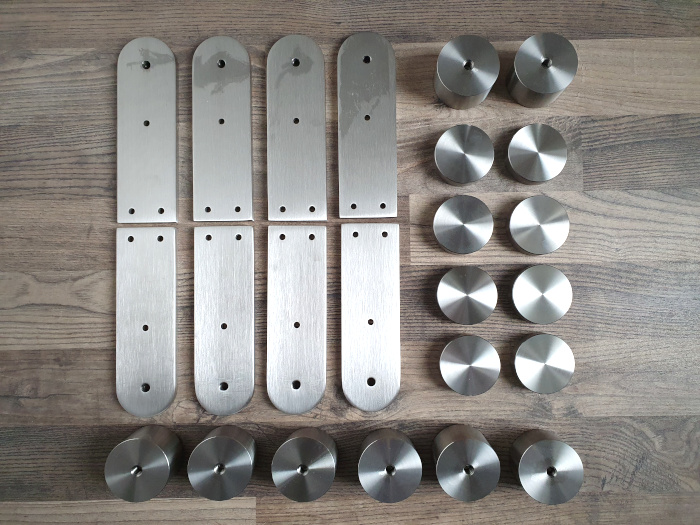
And the final AAI Estremo isolation hardware kit made to specification.
Change what is changeable, accept what is unchangeable, and remove yourself from the unacceptable.
(Denis E. Waitley)
Do you remember me quoting Jantzen Audio and their "No one can design a speaker´s crossover by using driver data alone and by software simulation"? Well, it was proven over and over again during the process.
The series resistor in the midrange could be a nice example. Simulation was perfect with it, but when it was removed and the topology corrected for the phase change again, much better purity and sweetness in the midrange was achieved, although the mids got boosted by 1.5dB between 400-700Hz. Although it certainly was a deviation from ideal measurements it sounded better, so there we went without the resistor and were pleased with the new sound.
A 200uF capacitor in the negative leg of woofers was another example. The value of 200uF was the best fit on the computer screen, yet, in my room, the bass was dull, it lacked punch, and hung in the room for longer than needed. We experimented to lower and increase the capacitor value by increments to find the best range (which we found between 175 and 183uF), and then moved by 1uF at a time to find the sweet spot, and further around the sweet spot to hit the sweetest spot (181.77uF). Jan of Silent Laboratories had to adjust the midrange resistors values too, to keep the phase accurate. Actually, every single change meant revisiting the phase alignment again. There are renowned voices on the internet that suggest that +/-1.0 to 3.0uF should make no audible difference as they are within the part tolerances anyway, which is a reasonable opinion. I can tell you that 0.5uF difference is audible. Partially it is the result of the part value tolerances that may change when the part is inserted in the neighbourhood of other parts, especially large coils, partially it is caused by changes in transient responses of the discharging capacitors. This puts a lot of strain on finding exact values, so each newcoming capacitor must be measured for its real value (that often deviates from the specified ones), and then recalibrated in the circuit to achieve the desired accuracy and left/right balance of the crossovers. It was also good to know that the L and R speaker values of the identical capacitor in the original TAD Evolution One crossover measured far apart. That perhaps explained why the in-room placement of TADs was not 100% symmetrical, while the new version listening triangle is micrometre-accuracy equilateral.
Identifying the right value was not the end, anyway. Some capacitors that we used were combinations of several units. For example, the 181.77uF that I mentioned was assembled from 100 + 68 + 10 + 3.3 + 0.47uF values, so we could also experiment with the make of each capacitor in this collection.
In the Part 3 of this journey, I mentioned the challenge of having the crossover components laid out in correct mutual orientation and spacing. This proved not less important than the component quality itself. It is ultra-important for coils, for they radiate strong EM fields that should ideally not interact (unachievable) or interact the way they do not cause audible issues (hard to achieve). Also, they can have the power to change capacitance value of the nearby capacitors, which can be a big problem cumulatively. So, although I wanted to have a nice and photogenic arrangement of the crossovers, we ended up with something that looks like the inside of a garbage can.
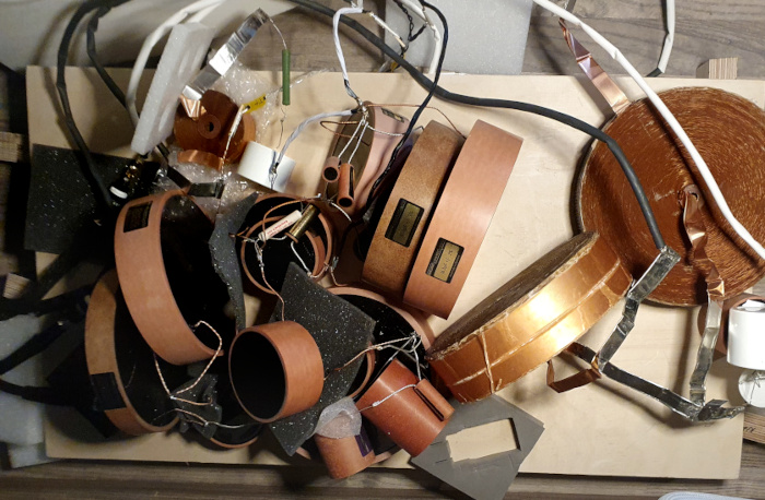
The golden rule of crossovers: The worse it looks, the better it sounds. But there was one advantage of having such a garbage can mess – we could work in three axes and were not limited by usual planar arrangement of surface mounted crossover boards.
Naturally, a lot of interactions were still going on. When one thing was optimized, another suffered. Measurements and simulations were a good starting point, but except the topology as such, most values and exact placements were fine-tuned by ear, often not in sync with what the computer screen showed. This has its explanation: the software simulates the exact on-the-screen topologies, but the values may drift as the parts start to radiate their EM fields when in mutual proximity. Also, the resolution of simulation programs is unable to show the audible difference between 10uF and 9 + 1uF. Everything had to be tested by listening sessions. It was a lengthy process with seemingly no end and lots of reiterations.
Duelund Pure Silver Bypass Capacitors
I must admit that these are quite powerful tools for final voicing. The only issue is that their effect is not predictable, and it must be tried and evaluated. The experience is not linear either. When the bypass is attached to a capacitor, you should be able to say whether it improved the sound or not. However, it happened to me quite a few times that one bypass was detrimental, but two attached to the very same capacitor sounded amazing. In the tweeter section, the Bypass cap had rather negative effect, no matter which capacitor it was attached to. The highs became softer and slightly diffuse, less articulated, which was against my intuition. On the other hand, the Bypass caps were wonderful in the midrange section, where I could sculpt the sound with high precision. I had 12 pieces available, and I used them all, some in pairs.

Duelund Pure Silver Bypass Capacitors
Directional wiring
In the previous part of this journey, I mentioned that we had been able to interconnect the crossover components with their leads and with as a few wires (AAI IST) as possible. As the casework was compact (by Revolution One standards) and the parts leads were long enough (thanks Duelund!), Jan managed to optimize the interconnecting wires to bare minimum; in fact, they were only used to connect “the first part in the signal path” to the appropriate binding post of bi-wireable speaker terminals. For instance, the interconnecting wires are completely absent in the tweeter’s section.
Still, as a perfectionist gardener, Jan reviewed the final crossovers once more for any excessive lengths of wires and pruned another 4.5 meters of material from them, be it hook up wire bundles or component leads. No need to say that everything was meticulously point-to-point soldered with Sn/Ag solder.
I should mention one important fact about AAI wires. After the IST Estremo treatment, I was warned, each wire piece became strictly directional. Ha, ha… Please note that I discuss a piece of solid core silver/copper wire with bare ends, there is no braiding, grounding, or shielding applied to it - it is just a plain wire that connects two spots in the crossover. In theory, there is no way it could be directional. But it was. When any of the AAI wires was reversed, the difference in sound was remarkable, nothing subtle. Technically speaking, it is not easy to say which direction the ‘signal’ in the crossover goes, so we tested the wires one by one in one and other direction to decide which sounded better.
A good and a bad day for Mundorf
The choice of resistors comes to personal preferences and to budget allowances. There are too many brands out there that it is impossible to try all. Although they were on hand, we had to skip Duelund Graphite Silver Resistors for the practical reasons – they are as long as pencils and quite fragile, and therefore we could not accommodate them anywhere in the crossover.
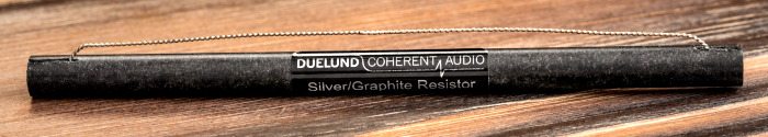
Duelund Graphite Silver Resistor
We also tested Path Audio resistors. They are beautifully made, and I used them in one of my previous projects, where they had crushed Mills, so I had high expectations. For the Revolution One, sonically they were not the best fit, however. Their fingerprint was too warm and smooth. So, we experimented with Mundorfs, from MOX, to Supreme and to Ultra.
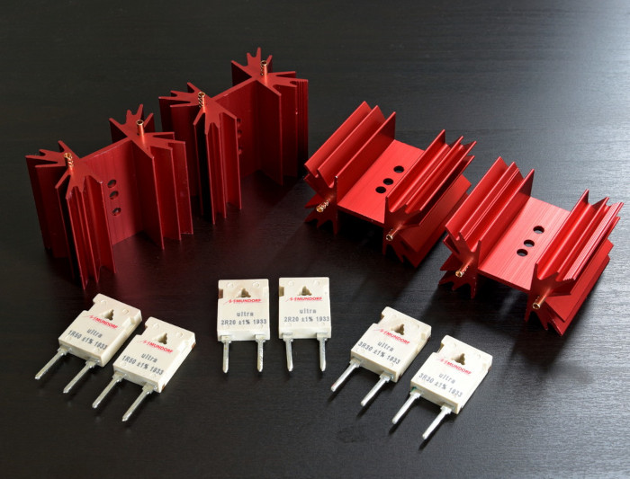
Mundorf MResist Ultra icluding heatsinks. Fantastic clean and open sounding resistors.
It was easy to tell the difference between MOX and MResist Supreme, although both had a sort of ‘Mundorf flavour’ which was a polar opposite of the Path Audio. They introduced extra spark and provided zesty sound which was quite attractive short-term, but there was perhaps too much electric haze and certain nervousness long-term. In photography analogy, these Mundorfs were like a slightly overexposed and grainy image. Therefore, we retired to using non-inductive MResist Ultra resistors which use copper-manganin foil and were truly excellent, transparent and flavourless. The best sounding resistors ever, in my opinion.
Although Mundorf provided superb clarity with resistors, we had less success with their capacitors. We needed two per channel, 22uF in the tweeter section and 68uF in the woofer section, where there was no physical room for a too large Duelund cap. Frankly speaking, we only had Mundorf’s MCap Aluminium EVO Oil caps on hand and did not test the MCap Silver Gold EVO version (which differs only by the material of the leads and costs fortune). We could not employ Supreme range - not only would such experiments be too expensive, but mainly because the Supreme range ends with values below 10uF and if we’d added up several capacitors to the total value, there wouldn’t been room enough inside the box. However, in the tweeter section the sound of the MCap EVO Oil was audibly compromised; it was lively but one-dimensional with a tad of stressful forwardness. Jan of Silent Laboratories suggested replacing the EVO Oils with his favourite Jantzen Z-Caps. We tried it and it was instrumental to hear how the sound got shaped when Jan went from Superior Z-Caps to Silver Z-Caps and even further to Alumen Z-Caps. After some iterations, we settled on Alumen Z-Caps that sounded the most natural and balanced and let the music breathe with richer textures, more vivid colours and finer details. In the bass section we left the Mundorf in place and decided to revisit it later if necessary.
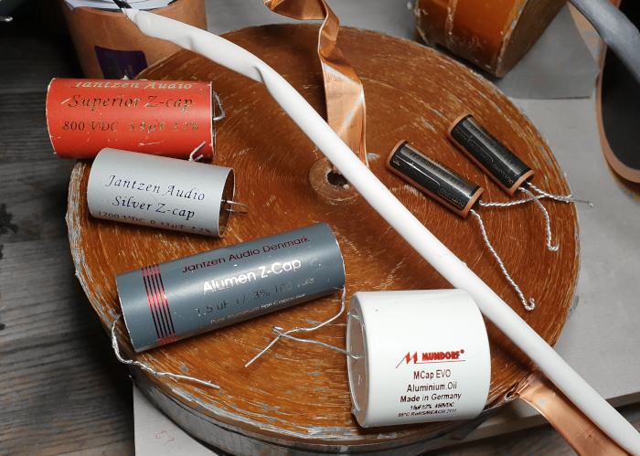
Three tiers of Jantzen Z-Caps and Mundorf MCap EVO Aluminium Oil.
Aero-padding
Provisionally, all the parts in the crossover case were secured by PUR foam and rubber pieces. Once the final positions (and orientations) or the parts were found, the foams were removed for I wanted to have as much air as possible inside and between the individual components and wires, as air is still the best dielectrics. To secure the parts in their positions, where needed, UHU Pattafix ProPower reusable glue pads were used. Unlike other plasticine-like materials it does not soften and run in heat (it remained stable even when I soldered in proximity of it) and is wonderful to stop resonances travelling through it. If I needed to separate components from each other, for example to prevent two bare leads touching, I used small cut-outs of open cell structure reticulated foam that is mostly air and minimum solids. This lightweight material is used in air filters and water filters. Removing all PUR foams was another small step towards better performance (yes, there was a tiny but audible difference), as well as it facilitated better air circulation inside the chassis.
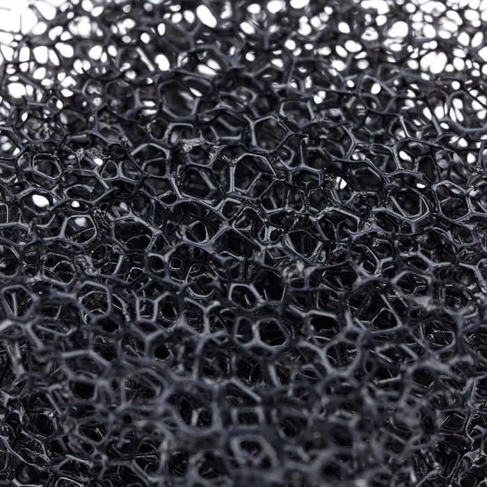
Aero-padding, as I nicknamed the reticulated open cell foam that has been used for separation of wires.
So, in the end, no stone left unturned. However, each stone was closely examined, evaluated and then returned, adjusted, or replaced. With the last drop of solder, the Revolution One crossovers were ready to rock.
To be continued...
Useful contacts:
Silent Laboratories – Jan Mixa, +420 777 772 642
Authentic Audio Image - AAI - +421 905 694 943
TAD Revolution One / Part 1 – Cabinets
TAD Revolution One / Part 2 – Crossover
TAD Revolution One / Part 3 – Crossover parts
TAD Revolution One / Part 4 – Casework and fine-tuning
TAD Revolution One / Part 5 – Finale
(C) Audiodrom 2024